Designing a 3D-Printed Hand-Tightened Collet-Style Ball Joint
The arm joint built previously made it possible to firmly fix front-to-back folding and height adjustments using 10mm square pipes. However, with the base completely fixed, there was a lack of flexibility to pull the arm out diagonally or swing it left and right to match the layout of the workspace.
To use a USB microscope comfortably for PCB work, a joint is needed at the base of the arm that allows for a certain degree of tilting and rotation. While adding a commercially available metal ball head was an option, it would lengthen the connection part with the 10mm square pipe and reduce rigidity. Therefore, I decided to 3D-print a custom ball joint that could be directly connected to the base.
Concept of a Spherical Joint with Fine Angle Adjustment at the Base
The objective this time is to place a compact ball joint at the base of the arm, allowing the upright angle of the entire arm to be freely and finely adjusted according to the conditions of the workbench.
As a future expansion, I have a concept to attach a DIN quick-release shoe to this base section, developing it into a structure that can be attached and detached with a single touch to a tripod or clamp socket. Therefore, in this prototype, I will first focus on establishing a robust collet chuck mechanism that can reliably hold the ball.
Specifications of the Spherical Joint for Secure Hand-Tightened Locking
The goals set for the design are as follows:
- Holding Force Target: Secure sufficient friction to prevent the angle from slipping down during work, with the entire arm weight and microscope attached to the tip.
- Range of Motion Target: Secure a range of motion of approximately 50 degrees as an angle that can be moved smoothly without interference for adjusting the tilt at the arm base.
- Operability Target: Enable complete locking and releasing simply by hand-tightening the outer ring nut, without using any tools such as hex wrenches.
Design of the Collet Chuck Structure and 3D-Printed Ball
Using the CAD software FreeCAD, I designed and printed each component using PLA filament. The approach adopted to solve the challenges is as follows:
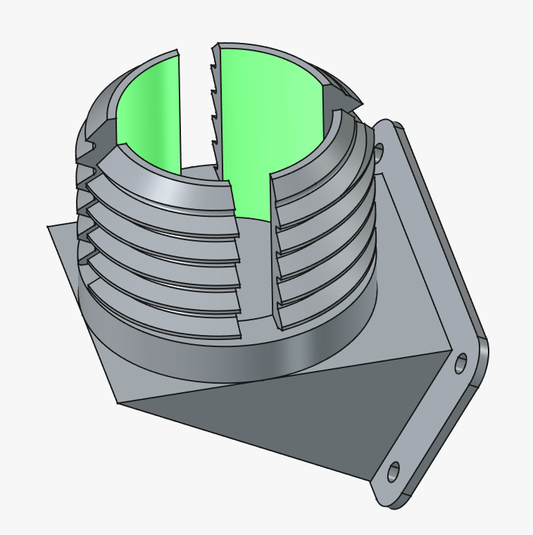
Collet Sleeve with Slits
I cut trapezoidal external threads on the outer periphery of the housing that holds the ball and created multiple deep vertical slits. By tightening the ring nut from the outside, the inner diameter shrinks uniformly as the slits narrow, adopting a collet chuck structure that wraps around the entire ball with uniform force. This efficiently converts high tightening torque into frictional force without concentrating excessive stress on a single point.
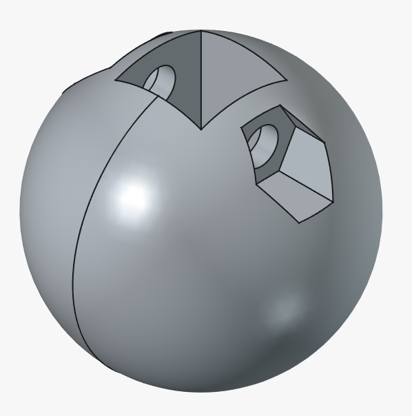
Integration of the 3D-Printed Ball and Square Pipe
The ball part to be gripped was also 3D-printed as a sphere. A shape that fits a 10mm square pipe was provided at the base of the ball, and it is fixed through with an M4 screw and nut. By modeling it as a single piece rather than repurposing a metal ball, both a strong connection with the pipe and appropriate clearance were achieved.
Thread Pitch Selection and Prototype Shape
The external threads were designed with a relatively coarse thread pitch to allow quick hand-tightening. Protrusions that are easy to grip by hand were provided on the ring nut side, ensuring that sufficient torque can be applied with just fingertip strength. Note that this prototype includes a wall-mounting flange (mounting tabs), which is a remnant of the initial wall-mounting assumption. Moving forward, I plan to improve this base shape and integrate it with the DIN quick-release shoe structure.
Collet-Type Ball Joint (Hand-Tightening) by nando-256 on Sketchfab
Confirming the 50-Degree Range of Motion and Secure Hand-Tightened Locking Force
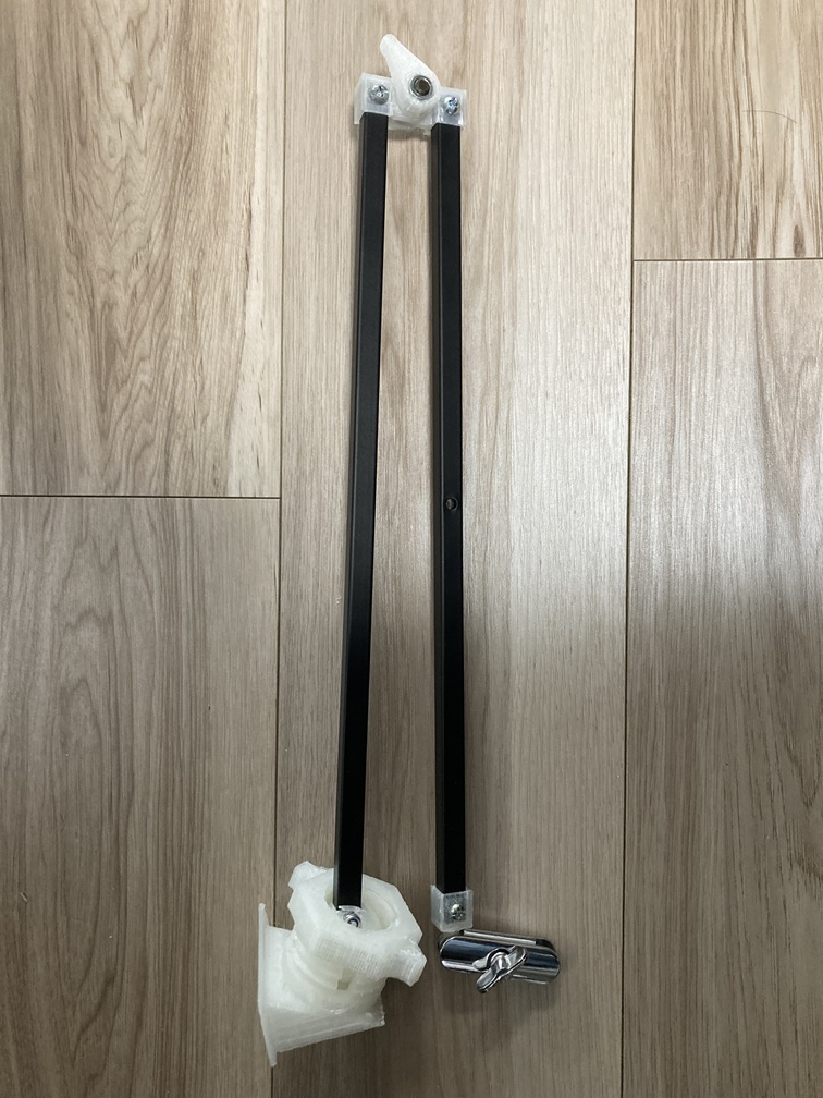
I assembled the printed parts, connected them to the 10mm square pipe, and verified the holding force and operability.
When aiming for a structure that allows the ball to move freely in all directions, the angle that could be moved ended up being approximately 50 degrees due to interference with the sleeve opening. While this does not allow for a large 360-degree pan-and-tilt in all directions, it is a sufficient range of motion for the purpose of fine-tuning the tilt and direction of the working position at the base of the arm.
Regarding the holding force, simply hand-tightening the outer ring nut securely supported its own weight even with the arm extended horizontally, bringing it to a complete standstill without wobbling. Because the collet structure tightens the ball evenly from all around, no signs of the sleeve cracking were observed even when applying strong hand-tightening torque, confirming extremely stable locking performance.
Conclusion
To enable fine-tuning at the base of the arm, a 3D-printed ball and collet-chuck housing were designed using FreeCAD and PLA. The uniform diameter-reduction structure utilizing slits achieved a holding force capable of firmly holding the arm using only a hand-tightened nut. Although the range of motion remained at around 50 degrees, practical rigidity and operability as an angle-adjustment jig at the base were confirmed.