Making a 3D-Printed DIY Tester Probe Holder
When checking board continuity or measuring voltage, holding both the positive and negative probes of a tester (multimeter) with both hands makes it impossible to secure the board, operate a stabilized power supply, or adjust an oscilloscope. Especially when working on surface-mount device (SMD) pins or narrow-pitch patterns, you often end up in a situation where you are one hand short.
While browsing the overseas e-commerce site AliExpress, I found a “multimeter probe holder" designed to bundle two tester probes like tongs so they can be operated with one hand. Judging by the photos, it looked like it was made using an FDM 3D printer, combining a simple spring mechanism with probe clips.

 https://link.amazon/B0fWt49PM
Designing and Making a Custom Jig Optimized for My Tester Probes
While purchasing a ready-made product was an option, if it didn’t match the shaft diameter of my probes, it would result in insufficient grip and looseness, or make tip alignment difficult. Furthermore, for a simple structure, modeling it to fit my own environment is faster, and allows me to adjust the spring tension to my liking.
Therefore, I decided to design a holder from scratch in 3D CAD so that it would be a perfect fit for my standard tester probes, and 3D print it myself.
Modeling and Printing with FreeCAD
I used FreeCAD as the design tool.
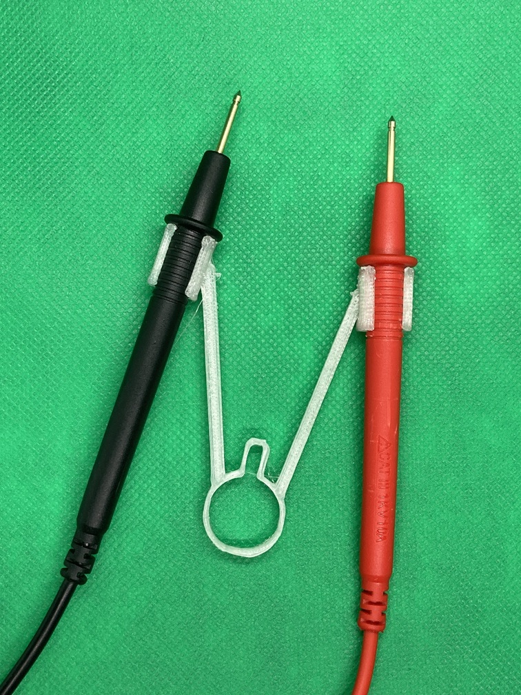
The overall structure consists of a leaf spring mechanism combining a circular ring and a U-shaped recess placed on the hand side, two arms extending from there toward the tip, and C-shaped holding clips at the tips.
For the outer dimensions, I referenced the overall dimensions listed in the AliExpress product description image (approx. 7.6 cm / 2.99 inches high, approx. 5.3 cm / 2.08 inches wide) to match the overall scale, making it easy to handle when held in the hand.
The C-shaped clips for holding the probes were designed with a 9 mm inner diameter, based on actual measurements of my probes’ grip diameters. The clip openings are made slightly narrower than the probe outer diameter, forming a snap-fit shape that clicks securely into place when pushed in.
To prevent delamination during printing, I placed the model flat on the bed in the slicer (laid completely flat along the XY plane). This ensures that the bending stress of the arms and the expansion stress of the clips are applied along the filament extrusion direction (fiber direction), securing sufficient mechanical strength for practical use. Standard PLA was used as the filament.
Usability of One-Handed Measurement and Improvements for Torsional Rigidity
Operational feel during actual pin measurement and issues with rigidity that became apparent
I attached the tester probes to the printed holder and tested it by measuring pins on a logic IC (SN74HC04N) on a breadboard.
The 9 mm inner diameter clips fit exactly as intended, holding the probes securely without any looseness. The repulsion force of the spring section was also just right, allowing me to smoothly control the distance between the probe tips using only the pressure of my fingertips. Because I could apply the probes to adjacent or opposing pins of a DIP IC with one hand, I was free to operate the power switch and oscilloscope with my other hand, significantly improving measurement work efficiency.
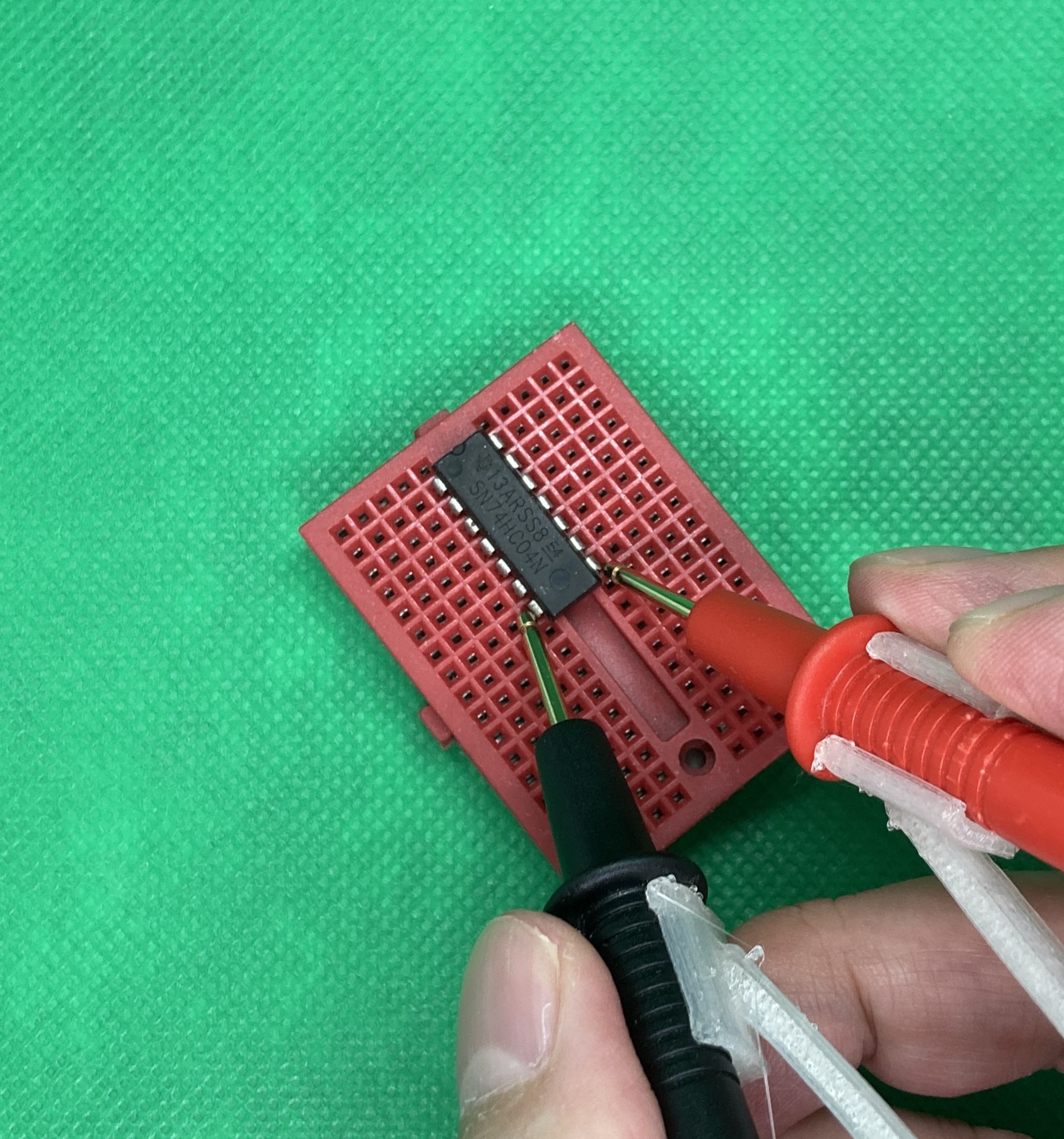
On the other hand, actual use revealed issues that need improvement. Because the plate thickness (height in the Z direction) was designed to be relatively thin, a slight distortion occurred in the “torsional direction (out-of-plane direction)" when the probe tips were pressed against the target object. While there is sufficient resilience in the opening and closing direction of the spring, torsional rigidity is lacking when loads are applied at an angle. For this point, increasing the height of the spring and arm sections in the Z direction is expected to reinforce the torsional rigidity.
The 3D model created this time is scheduled to be published on Sketchfab for visual verification. As for distributing the 3D data downloads, I am considering providing them via BOOTH or Patreon after making improvements such as enhancing rigidity.
 https://link.amazon/B0dmHQpgN
Conclusion
To improve the efficiency of tester measurements where both hands are occupied, I designed and built a custom probe holder in FreeCAD, referencing the product dimensions from AliExpress (approx. 7.6 cm high, 5.3 cm wide). With a 9 mm inner diameter C-clip and flat-bed PLA printing, I achieved sufficient holding power and appropriate springiness suitable for my probes, enabling stable one-handed measurements. Regarding the torsional distortion caused by insufficient Z-axis thickness found during practical testing, I plan to improve the rigidity through design changes to increase arm height, and proceed with releasing the data via Sketchfab and other platforms.