How to Create SVG Data for 3D Printers from JPG or PNG Images Using Inkscape
When utilizing digital fabrication tools such as 3D printers and laser cutters, vector data (such as SVG or DXF) that outlines the reference contours is indispensable. However, many of the image files easily accessible on a daily basis—such as free materials from the internet or illustrations prepared yourself—are in raster formats (collections of pixels) like JPG or PNG. These image files cannot be used directly as foundational data for creating 3D models in 3D CAD software.
Converting Your Images for Use in CAD
This article explains how to use Inkscape, an open-source vector graphics editor, to convert common image files like JPG and PNG into the SVG format, which can be imported into 3D CAD software such as FreeCAD.
The Pitfalls of Direct 3D Conversion and Scale Mismatch for Image Data
3D CAD software like FreeCAD lacks the ability to automatically recognize the boundaries of imported raster images and extrude (volumize) them. Furthermore, even if a successful conversion to SVG is achieved, making significant scale (dimension) adjustments after importing into CAD software tends to complicate operations and easily induce design errors. You must ensure that the dimensions match the intended actual size (e.g., 100 mm, which is the printing limit of a 3D printer) right at the moment of importing into the CAD.
Procedure for SVG Conversion in Inkscape
To resolve the aforementioned challenges, perform image conversion and size adjustment according to the following steps. Proceed with the work after installing the software from the official Inkscape website ( https://inkscape.org/ja/ ).
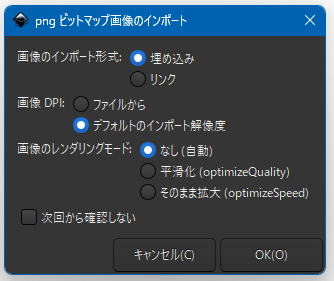
- Importing the image: Launch Inkscape, select “Import" from the “File" menu, and place the target PNG or JPG image onto the canvas. The import options can be left as they are.

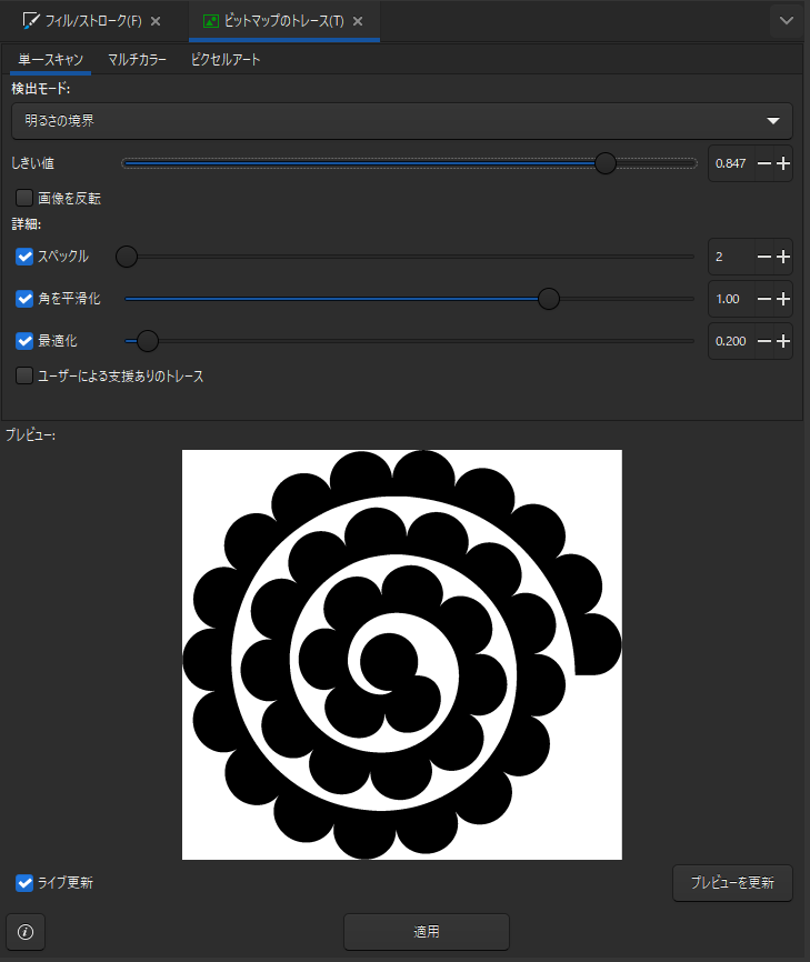
- Trace Bitmap: With the image selected, open “Trace Bitmap" from the “Path" menu. Select “Brightness Threshold" under “Single scan", adjust the threshold to find a value where the contours are clearly displayed in black, and execute “Apply".

- Deleting the original image: Move the generated path (vector data) to the side, select the underlying original raster image, and delete it.
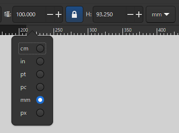
- Real-world size adjustment: Adjust the size before saving. Change the unit to “mm" in the tool control bar at the top of the screen and enable the lock icon to preserve the aspect ratio. Then, enter the desired actual dimension (e.g., 100) in the width or height input field.

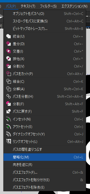
- Simplifying the path: To lighten the processing load in CAD software, with the path selected, execute “Simplify" from the “Path" menu to reduce unnecessary nodes without compromising the shape. *This is optional.

- Specifying the save format: From the “Save As" option in the “File" menu, set the file type to “Plain SVG" rather than “Inkscape SVG" before saving.
Achieving Seamless Integration with CAD and Maintaining Accurate Dimensions
By carrying out this sequence of steps, vector data that accurately captures the image contours was generated. Adjusting to the actual size in Inkscape prior to saving and outputting in the Plain SVG format made it possible to obtain extremely manageable foundational data that prevents dimensional discrepancies or import errors even when imported into external software such as FreeCAD.
Conclusion
We explained the method of using Inkscape to convert JPG and PNG images into SVG to prepare vector data for use in 3D printers and similar devices. Since CAD cannot turn images directly into 3D models, automatic tracing to create paths is essential. By establishing the procedure of adjusting to actual size in Inkscape immediately after conversion and saving as a Plain SVG, you can prevent CAD import errors and scale mismatches, enabling the creation of clean data that smoothly links to subsequent processes.