[RP2350] Blinking an LED in Arduino IDE with the Pico 2-compatible “16MB Ultimate Edition”
While window shopping on AliExpress, a development board with a built-in USB Type-A male connector suddenly caught my eye.
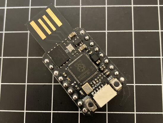
Taking a closer look, the onboard chip is the talked-about RP2350. I’ve played with the Raspberry Pi Pico (RP2040) many times before, but its successor, the RP2350, is entirely new to me. Featuring a “latest-generation chip" combined with a “cable-free direct-plug style," these two elements drew me in, and before I knew it, I had added it to my cart and checked out. A pure impulse buy.
What arrived was a board with a typical no-frills Chinese product name: “Development Board Module For Raspberry PI Dual Core 16MB." You also can’t overlook the fact that it packs a massive 16MB flash memory—four times the capacity of the official Pico 2.
Since I now have it on hand, I want to try out various things using this unique board. Let’s start by tackling the alpha and omega of electronics prototyping: blinking an LED.
Getting the Board Ready for Use
While this board looks sleek and smart like a USB flash drive, it comes with neither manuals nor support. The goal this time is to set up an environment where this “mystery RP2350 board" is recognized by the Arduino IDE and can be programmed freely.
Specifically, we will clear the following three quantitative goals:
- Environment Setup: Make the Arduino IDE recognize the RP2350 and configure it to fully utilize the 16MB storage space.
- Flashing: Plug it directly into a USB port cable-free and transfer the program.
- LED Blinking: Control and blink the onboard LED (details unknown).
Installing the Unofficial Core (Earle Philhower Version)
The standard board definitions in the Arduino IDE may not yet fully support the RP2350 or might have restricted features. Therefore, we will install a feature-rich community core definition.
Preferences: Open “File" > “Preferences" from the Arduino IDE menu.
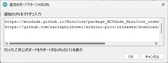
Adding the URL: Paste the following URL into the “Additional boards manager URLs" field.
https://github.com/earlephilhower/arduino-pico/releases/download/global/package_rp2040_index.json
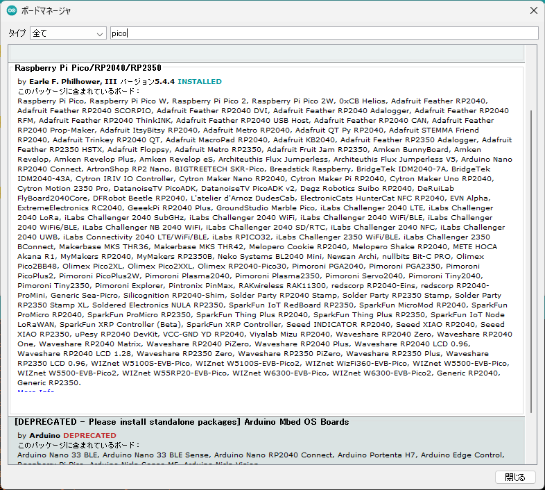
Installation: Open the “Boards Manager" on the left side and type `pico` into the search bar. Install “Raspberry Pi Pico/RP2040 by Earle F. Philhower, III" from the search results. *Note: Make sure the version is 4.0.0 or higher (older versions will not display the RP2350).
Select “Generic" for Board Settings
This is the most crucial point for utilizing the full 16MB. If you select “Raspberry Pi Pico 2," you will only be able to use 4MB.
- Board: Select `Generic RP2350`.
- Flash Size: Choose an option added to the menu, such as `16MB (Sketch: 16MB / FS: 0MB)`.
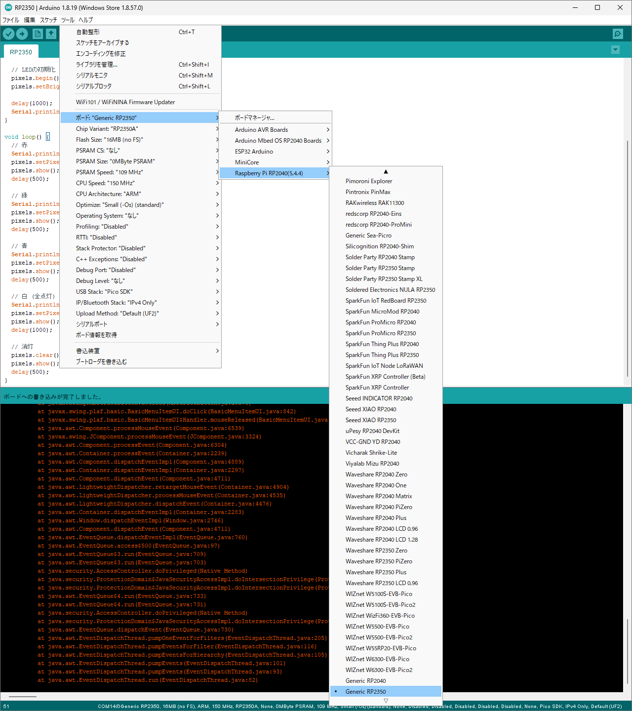
With this, compilation preparation is complete.
The “Not Recognized" PC Connection Issue and Its Solution
Full of enthusiasm, I plugged it into my PC’s USB port, but the PC didn’t respond at all. It didn’t show up in the Device Manager, nor did it appear in the Arduino IDE port list. I panicked, thinking, “Could it be a dead on arrival (DOA) unit?" However, in my environment, taking the following steps made it successfully recognized.
Manual Flashing for the “First Time Only"
In my case, the issue was resolved by following these steps:
- Connect via BOOT Button: Plug it into the USB port while holding down the “BOOT" button on the board. A folder (drive) named “RP2350" will open.
- Drop the File: “Export compiled binary" in the Arduino IDE, and drop the generated `.uf2` file into that folder.
- Automatic Recognition Thereafter: Once you successfully flash it using this method once, it will be recognized simply by plugging it in as “COM14 (Raspberry Pi Pico 2W)" without needing to press the BOOT button from then on.
Presumed Cause
It is likely that right after purchase (or in a state with no program flashed), the functionality required to communicate with a PC is not running, which is why it wasn’t recognized as a COM port. Flashing a program manually enabled the USB communication function inside the program, allowing the PC to recognize it.
Implementing LED Blinking: The LED is a “NeoPixel" on “GP22"
The number “22" was printed in small text near the LED on the board. Furthermore, based on the component’s shape, it turned out to be a “NeoPixel (WS2812B)" rather than a standard LED. By installing the `Adafruit NeoPixel` library and specifying pin number 22, I successfully achieved a vibrant 3-color LED blink.
Please install the library to use the NeoPixel LED:
Tools > Manage Libraries > Install Adafruit NeoPixel
#include <Adafruit_NeoPixel.h>
// — Configuration Area —
// Specify pin 22 as printed on the board
const int RGB_LED_PIN = 22;
const int NUM_PIXELS = 1;
// Create NeoPixel object
Adafruit_NeoPixel pixels(NUM_PIXELS, RGB_LED_PIN, NEO_GRB + NEO_KHZ800);
void setup() {
  Serial.begin(115200);
  // Initialize LED
  pixels.begin();
  pixels.setBrightness(30); // Low brightness
  delay(1000);
  Serial.println("\n— GPIO 22 LED Test Start! —");
}
void loop() {
  // Red
  Serial.println("Red");
  pixels.setPixelColor(0, pixels.Color(255, 0, 0));
  pixels.show();
  delay(500);
  // Green
  Serial.println("Green");
  pixels.setPixelColor(0, pixels.Color(0, 255, 0));
  pixels.show();
  delay(500);
  // Blue
  Serial.println("Blue");
  pixels.setPixelColor(0, pixels.Color(0, 0, 255));
  pixels.show();
  delay(500);
  // White (All on)
  Serial.println("White");
  pixels.setPixelColor(0, pixels.Color(255, 255, 255));
  pixels.show();
  delay(1000);
  // Turn off
  pixels.clear();
  pixels.show();
  delay(500);
}
Conclusion
At one point I doubted whether the direct-plug USB board was broken, but by performing the “initial ritual (flashing in BOOT mode)," I was able to successfully control it from the Arduino IDE.
- Lesson Learned: Don’t panic if a newly purchased RP2350 isn’t recognized. First, breathe life (a program) into it using the BOOT button.
This vast open space of “16MB" and the power of the RP2350. The warm-up exercises are complete. Next time, I plan to add an SD card slot to this board and evolve it into a “data logger."