【RP2350】No SD Card Module Required! Read and Write Data by Reusing a Spare Conversion Adapter
Following our setup of the RP2350 board last time, today we’ll take on the challenge of reading and writing data to an SD card.
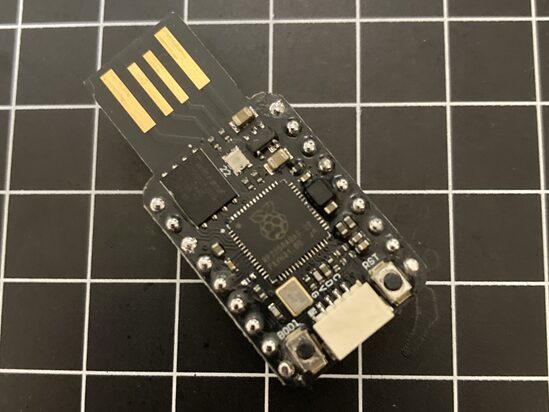
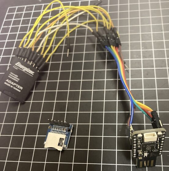
While an SD card is essential for recording sensor data and saving configuration files, you typically purchase a dedicated connection module to use one. However, if you have any leftover “SD card conversion adapters" that come with MicroSD card purchases, you can modify one and use it as a slot.
In this post, I’ve compiled the steps for reading and writing data with the RP2350 using a spare adapter at hand, without buying an extra dedicated module. I’ll also share my personal soldering tips for wiring heat-sensitive plastic adapters without ruining them.
First, Verify Operation with a Commercial Module
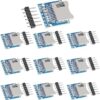
If you jump straight into testing a homemade slot and it doesn’t work, it’s impossible to isolate whether the issue lies in the wiring or the program. First, I ran a communication test with the RP2350 using a commercially available SD card module I had on hand.
 https://www.amazon.co.jp/Youmile-カードモジュールマイクロ-カ...
While this is a reassuring design featuring a 3.3V/5V level shifting chip, the RP2350 (3.3V) can operate even with a direct connection.
Introducing the “SdFat" Library
Before running tests, install the library for handling SD cards in the Arduino IDE. This time, we will use SdFat, which is highly functional and works great with the RP2350.
- Open the Arduino IDE menu and go to “Tools" -> “Manage Libraries…".
- Search for SdFat and install it.
I performed a read/write test using this library and confirmed that it works properly. Great, now the microcontroller and software setup are complete.
Attempting Direct Soldering to the Conversion Adapter
Now, this is where the real work begins. The terminals of the conversion adapter are gold-plated, making it easy for solder to adhere… or so you’d think, but the base is made of heat-sensitive plastic. If you hesitate, heat will conduct and deform the inside, making it impossible to insert an SD card.
While the conventional wisdom has been to “solder with a dummy SD card inserted to prevent deformation," I solved this using the power of tools and chemistry.
Nando Kobo Style: The Secret to Soldering Without Melting
The key to success is “minimizing the time heat is conducted to an absolute minimum." To achieve this, I used the following tool.
Using a toothpick or similar tool, dab just a small amount of this onto the tips of the adapter’s terminals.
Since there are no wires in the way, your hands won’t slip, allowing you to hit the exact target spot in one go.
[Procedure]
- Apply paste to the tips of the terminals.

- Pre-tin the soldering iron tip with a little solder.
- Briefly touch the iron to the pasted area. The required time is 0.5 seconds!
- Thanks to the effect of the paste, the solder flows smoothly onto the terminal instantly.
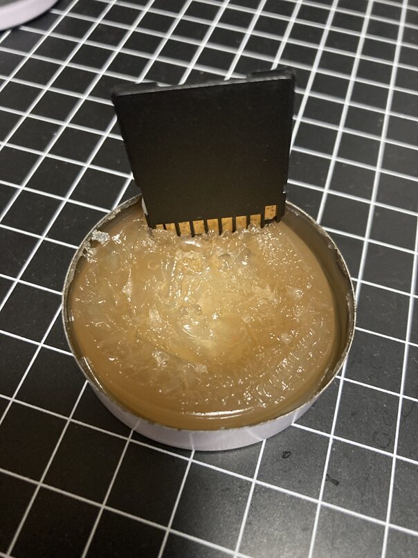
With this method, the job finishes before heat can conduct to the plastic part (the base), preventing deformation even without inserting a dummy card. “Soldering is about speed, not temperature." This was the moment I truly realized that.
Wiring and Program
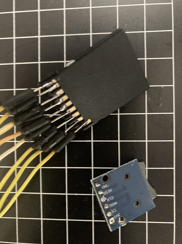
Connect the completed “DIY SD slot" to the RP2350.
[Wiring Diagram] (*Pin assignment with the terminal side facing you and the corner notch of the adapter in the upper left)
| Adapter Terminal (from left) | Signal Name (SPI) | RP2040-Zero | Role |
| Pin 9 (Far Left) | DAT2 | (Not Connected) | Not used in SPI |
| Pin 1 (2nd) | CS / DAT3 | GP 5 | Chip Select (Selecting communication partner) |
| Pin 2 (3rd) | MOSI / CMD | GP 7 | Data Transmit (Microcontroller -> SD) |
| Pin 3 (4th) | VSS1 (GND) | GND | Ground *1 |
| Pin 4 (5th) | VDD | 3V3 | Power Supply (3.3V) |
| Pin 5 (6th) | SCK / CLK | GP 6 | Clock (Communication timing) |
| Pin 6 (7th) | VSS2 (GND) | GND | Ground *1 |
| Pin 7 (8th) | MISO / DAT0 | GP 4 | Data Receive (SD -> Microcontroller) |
| Pin 8 (Far Right) | DAT1 | (Not Connected) | Not used in SPI |
Test Program
We use the same code verified in Step 1. *Note: When using the SdFat library, use the class name SdFile instead of File.
#include <SPI.h>
#include "SdFat.h"
// — Pin configuration (RP2350 / Pico 2) —
// Uses the same pin layout as the RP2040
const int PIN_MISO = 4;
const int PIN_CS = 5;
const int PIN_SCK = 6;
const int PIN_MOSI = 7;
// SdFat configuration
SdFat sd;
SdFile myFile;
void setup() {
Serial.begin(115200);
// Wait for serial connection
while (!Serial) { yield(); }
delay(1000);
Serial.println("
— RP2350 (Pico 2) SPI SD Card Test —");
// Display chip information (useful for blog screenshots)
Serial.print("Board Target: ");
#if defined(ARDUINO_ARCH_RP2040)
Serial.println("RP2040 / RP2350 Architecture");
#else
Serial.println("Unknown Architecture");
#endif
// 1. SPI pin assignment (This function is also valid on the RP2350)
SPI.setRX(PIN_MISO);
SPI.setTX(PIN_MOSI);
SPI.setSCK(PIN_SCK);
Serial.println("Initializing SD card…");
// 2. SD card initialization
// The RP2350 is fast, but let’s test connection at a stable 16MHz first
if (!sd.begin(PIN_CS, SD_SCK_MHZ(16))) {
Serial.println("Error: SD card initialization failed.");
Serial.println("- Check wiring?");
Serial.println("- Check format (FAT32)?");
sd.initErrorHalt(&Serial);
return;
}
Serial.println("Success: SD card initialized!");
// — Write test —
Serial.print("Writing test.txt… ");
if (!myFile.open("test_rp2350.txt", O_RDWR | O_CREAT | O_APPEND)) {
Serial.println("Error: Failed to open file for writing.");
return;
}
// Record that the write is coming from the RP2350
myFile.println("Hello from RP2350 (Pico 2)! SPI write test successful.");
myFile.close();
Serial.println("Done.");
// — Read test —
Serial.println("Reading test.txt content:");
Serial.println("————————-");
if (!myFile.open("test_rp2350.txt", O_READ)) {
Serial.println("Error: Failed to open file for reading.");
return;
}
while (myFile.available()) {
Serial.write(myFile.read());
}
myFile.close();
Serial.println("
————————-");
Serial.println("Test Complete.");
}
void loop() {
// Do nothing
}
Investing in Tools Leads to DIY Success
Buying a cheap SD module for a few hundred yen is also a valid approach, but utilizing a conversion adapter you have on hand gives you the advantage of freely deciding the layout and orientation of the slot. Above all, I gained valuable experience knowing that “with the right flux, even difficult soldering jobs can be finished in an instant."
This establishes an environment for reading and writing large volumes of data. Next time, I’ll try high-speed reading and writing using PIO SDIO with this SD card adapter.