I Looked into How to Create Custom Pinout Images

When checking the pinout of electronic components, store listing images are helpful, but reusing them directly may raise copyright concerns. Therefore, I decided to look for a tool that allows me to create my own.

目次

Investigating Tools for Creating Pinout Images

I tried the following tools:

GenPinoutSVG Performed Closest to What I Expected

After trying these tools, I found that GenPinoutSVG was the closest to the behavior I wanted.

This tool allows you to generate pinout images in SVG format by writing pinout information into a CSV file. Its appeal lies in its ease of customization and simple structure, making it very manageable.

How to Use GenPinoutSVG

GenPinoutSVG requires the following python3 libraries:

svgwrite==1.2.1(Graphical_Datasheetsで要求されていたバージョンで動いた)
docpt
wand

Additionally, you need to install the following Ubuntu package:

sudo apt install libmagickwand-dev

Once the installation is complete, specify the CSV file containing the pinout information and run it, which will generate an SVG file with the same name inside the svg directory.

python3 GenPinoutSVG.py data/RP2040-zero.csv

LABELS,DEFAULT,TYPE,GROUP,Name, Official Name, GPIO, Analog 1, Analog 2, RTC, Func 1, Func 2, Func 3 BORDER COLOR, grey BORDER WIDTH, 2 BORDER OPACITY, 1 # FILL COLOR, white, white, white, white, deepskyblue, black, yellow, green, cornflowerblue, plum, yellow, grey FILL COLOR, white, white, white, white, deepskyblue, gray, yellow, limegreen, cornflowerblue, plum, yellow, grey OPACITY, 1, 1, 1, 1, 1, 1, 1, 1, 1, 1, 1, 1 FONT , Rubik, , , Work Sans, Work Sans FONT SIZE , 25, , , 25, 25 # FONT COLOR , black, , , , , white FONT COLOR , black, , , , , FONT SLANT , normal , , , , , FONT BOLD , 700 , , , 700 FONT STRETCH , normal # FONT OUTLINE , yellow , , , , blue FONT OUTLINE , black , , , , FONT OUTLINE THICKNESS, 0.1 BOXES, STD, , , PIN BOX, NAME BOX, SKEWED, SKEWED, SKEWED, SKEWED, SKEWED, SKEWED, SKEWED TYPE, IO, black, 1 TYPE, INPUT, black, 1 TYPE, OUTPUT, black, 1 WIRE, DIGITAL, black, 1, 5 WIRE, PWM, black, 1, 5 WIRE, ANALOG, black, 1, 5 WIRE, HS-ANALOG, black, 1, 5 WIRE, POWER, black, 1, 10 GROUP, ESP32 VSDIO, fuchsia, 0.5 GROUP, ESP32 RTC, chartreuse, 0.5 GROUP, ESP32 VIO, deepskyblue, 0.5 GROUP, SAML21 VDDANA, khaki, 0.5 GROUP, SAML21 VDDIO, khaki, 0.5 GROUP, COMBINED, chocolate, 0.5 GROUP, POWER, black, 0 GROUP, NONE, grey, 0.1 BOX, STD, black, 1, white, 0, 1, 100,55,2,2,0,0 BOX, PIN BOX, black, 1, white, 0, 1, 80, 55, 5, 5, -10, 0 BOX, NAME BOX, black, 1, white, 0, 1, 125, 55, 5, 5, -10, 0 BOX, SKEWED, black, 1, white, 0, 1, 125,55,5,5,-10,0 BOX, PAGE BORDER, black, 1, white, 1, 50, 100,100,0,0,0,0 BOX, DETAIL BOX, darkblue, 1, white, 0, 3, 250, 200, 15,15,0,0 TEXT FONT, PowerPin, Dejavu Sans, 25, , black, normal, bold, normal TEXT FONT, Heading, BenchNine, 50, , black, normal, 700, normal PAGE, A4-L DPI, 300 DRAW # Load up the fonts we use GOOGLEFONT,"https://fonts.googleapis.com/css?family=BenchNine:300,400,700|Pragati+Narrow:700|Rubik|Ruslan+Display|Work+Sans:700,800,900″ # Draw a border on the page BOX, PAGE BORDER, 0,0, 100%, 100% # Left Side Pins ANCHOR, 1000,100 PINSET, LEFT, PACKED, CENTER, CENTER, 74.75, 30, 45, 60, 10, 0 PINTEXT, POWER, OUTPUT, POWER, 5V, PowerPin, PINTEXT, POWER, IO, POWER, GND, PowerPin, PINTEXT, POWER, OUTPUT, POWER, 3.3V , PowerPin, PIN, POWER , IO,,GP29,ADC3,,,,,,, PIN, POWER , IO,,GP28,ADC2,,,,,,, PIN, POWER , IO,,GP27,ADC1,,I2C1 SCL,,,,, PIN, POWER , IO,,GP26,ADC0,,I2C1 SDA,,,,, PIN, POWER , IO,,GP15,,SPI1 SCK,I2C1 SDA,,,,, PIN, POWER , IO,,GP14,,SPI1 TX,I2C1 SDA,,,,, # Right Side Pins ANCHOR, 1100,100 PINSET, RIGHT, PACKED, CENTER, CENTER, 74.75, 30, 45, 60, 10, 0 PIN, POWER , IO,,GP0,,SPI0 RX,I2C0 SDA,UART0 TX\n(def.),,,, PIN, POWER , IO,,GP1,,SPI0 CSn,I2C0 SCL,UART0 RX\n(def.),,,, PIN, POWER , IO,,GP2,,SPI0 SCK,I2C1 SDA,,,,, PIN, POWER , IO,,GP3,,SPI0 TX,I2C1 SCL,,,,, PIN, POWER , IO,,GP4,,SPI0 RX,I2C0 SDA,UART1 TX,,,, PIN, POWER , IO,,GP5,,SPI0 CSn,I2C0 SCL,UART1 TX,,,, PIN, POWER , IO,,GP6,,SPI0 SCK,I2C1 SDA,,,,, PIN, POWER , IO,,GP7,,SPI0 TX,I2C1 SCL,,,,, PIN, POWER , IO,,GP8,,SPI1 RX,I2C0 SDA,UART1 TX,,,, PIN, POWER , IO,,GP9,,SPI1 CSn,I2C1 SCL,UART1 TX,,,, PIN, POWER , IO,,GP10,,SPI1 SCK,I2C1 SDA,,,,, PIN, POWER , IO,,GP11,,SPI1 TX,I2C1 SCL,,,,, PIN, POWER , IO,,GP12,,SPI1 RX,I2C0 SDA,UART0 TX,,,, PIN, POWER , IO,,GP13,,SPI1 CSn,I2C0 SCL,UART0 TX,,,, # Right Side Pins ANCHOR, 2100,100 PINSET, RIGHT, PACKED, CENTER, CENTER, 74.75, 30, 45, 60, 10, 0 PINTEXT, POWER, IO, POWER, GND, PowerPin, PIN, POWER , IO,,GP25,,,,,,,, PIN, POWER , IO,,GP24,,,,,,,, PIN, POWER , IO,,GP23,,,,,,,, PIN, POWER , IO,,GP22,,,,,,,, PIN, POWER , IO,,GP21,,,I2C0 SCL,,,,, PIN, POWER , IO,,GP20,,,I2C0 SDA,,,,, PIN, POWER , IO,,GP19,,SPI0 TX,I2C1 SCL,,,,, PIN, POWER , IO,,GP18,,SPI0 SCK,I2C1 SDA,,,,, PIN, POWER , IO,,GP17,,SPI0 CSn,I2C0 SCA,UART0 RX,,,,

The generated SVG image is shown below.
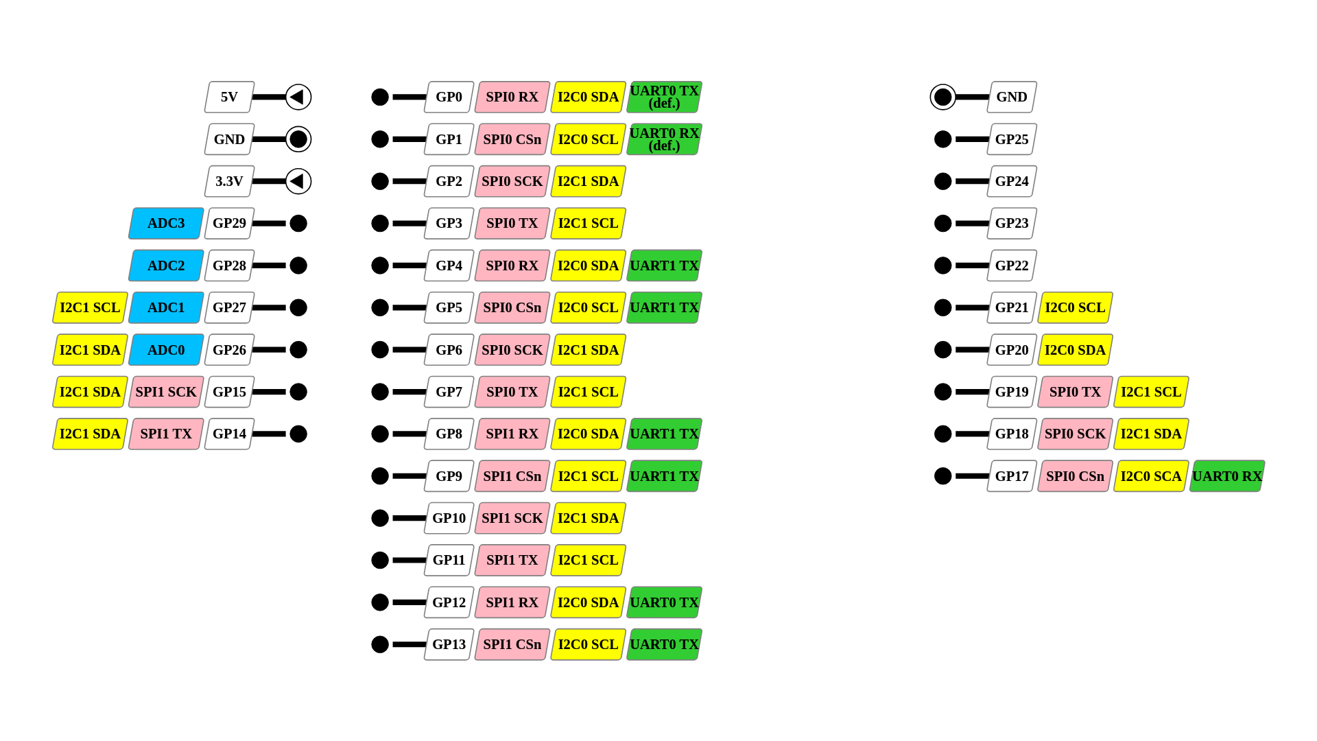
RP2040-zeroもどきのピンアサインのみ

Overlaying the SVG Image onto a Photo

By overlaying the created SVG image onto an actual photo of the electronic component, I made the pinout visually clearer. This allows for a more intuitive understanding of the pin layout. I used Canva for image overlay and composition.
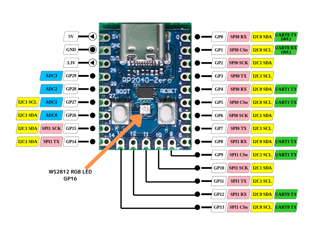
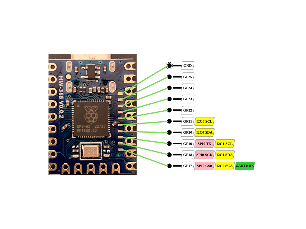
RP2040-zeroもどきのピンアサインRP2040-zeroもどきの裏のピンアサイン

Might There Be an Even Better Tool?

However, it appears that GenPinoutSVG is currently no longer maintained. There may be newer and more user-friendly tools available.

In particular, if there is a tool that allows pin information to be written in JSON or YAML instead of CSV, it would enable more flexible data management, so I would like to continue investigating if such a tool exists.

If I find any new tools in the future, I will be sure to introduce them.