Overcoming Parallel Import mBot Troubles! Building a Custom Bluetooth RC Car with Raspberry Pi Zero W
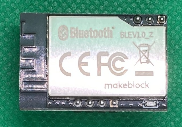
I purchased an mBot educational robot kit on Amazon. It had a reputation for being ideal as an introduction to visual programming for children, so I assembled it with great excitement, but what arrived turned out to be a parallel import. Upon checking the Bluetooth module, I noticed it lacked the Technical Conformity Mark (Telec certification). Powering it on as-is would transmit illegal radio waves, so I decided to remove the Bluetooth module and operate it without it.
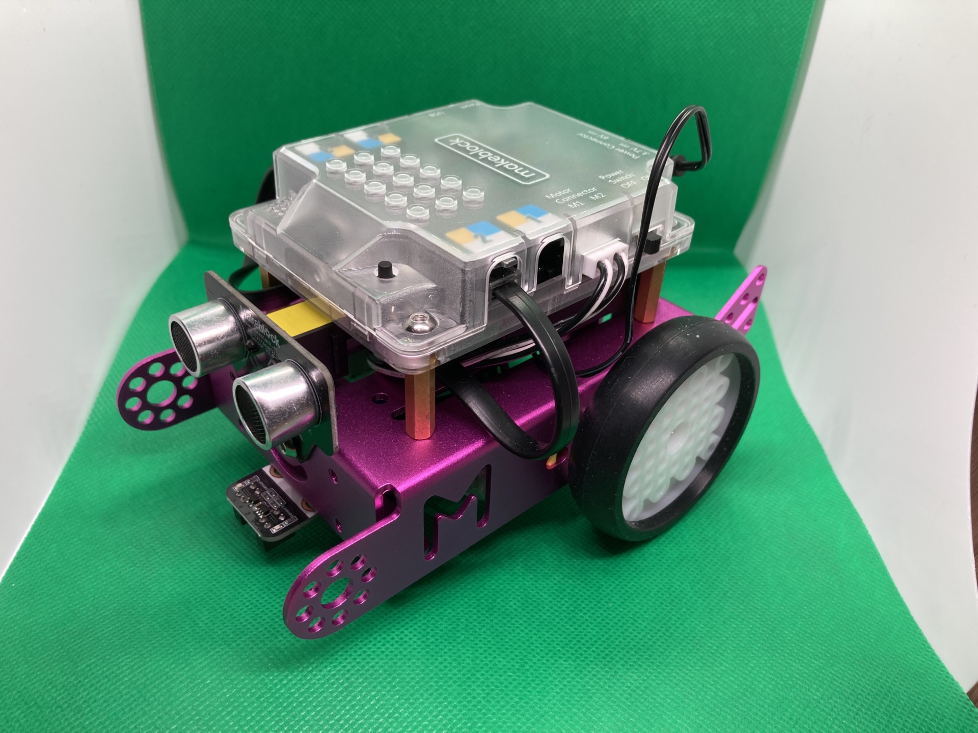
As a result, wireless control from a smartphone or tablet—my original goal—was abandoned. Only the initial features remained: remote control via an infrared remote, line follower mode, obstacle detection mode using an ultrasonic sensor, and program writing via a USB cable. Gritting my teeth with the frustration of “If I can’t use Bluetooth…", an idea suddenly flashed through my mind—
“If mBot doesn’t work out, why not just build a robot with Bluetooth connectivity myself?!"
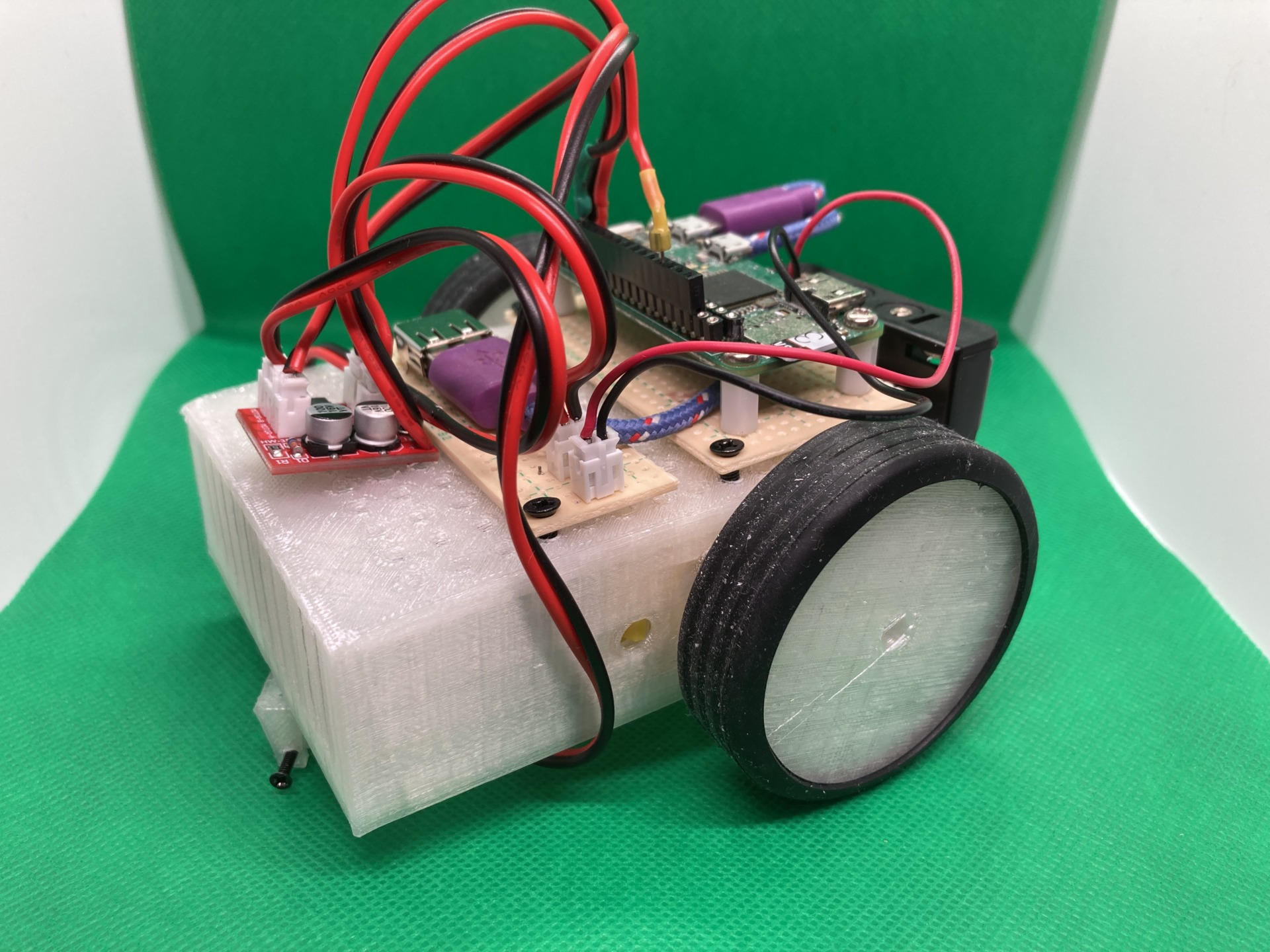
Thus, sparked by the parallel import trouble, a custom RC car project began, combining a Raspberry Pi Zero W, commercially available DC motors, and a 3D-printed chassis. Using a Raspberry Pi Zero W, I built an RC car that drives DC motors with an MX1508 (L298-equivalent) control board. By combining a chassis and wheels designed and output with a 3D printer and silicone rubber tires from a 100-yen shop, I was able to create a robust body while keeping costs down. The Bluetooth remote is read using the evdev library, and smooth motor control is achieved via pigpio's hardware PWM function.
The Challenge
The pink mBot sold on Amazon appeared to be a parallel import, and its Bluetooth module did not have the Technical Conformity Mark. Using it as-is would emit illegal radio waves, so I am using it with the module removed.
The Solution
① Build a robot equipped with Bluetooth connectivity using a Raspberry Pi Zero W.
② Replace mBot’s built-in GUI-based movement assembly features with a visual flow editor like Node-RED.
This time, we will implement approach ①.
Materials List
- Raspberry Pi Zero W (with the latest Raspberry Pi OS installed)
- MX1508 Motor Driver Module (2-channel, 1.8–5 V drive)
MX1508
- DC Motors ×2 (for axles)
Motor - 3D-printed Chassis and Tire Wheels (custom data printed via 3D printer)
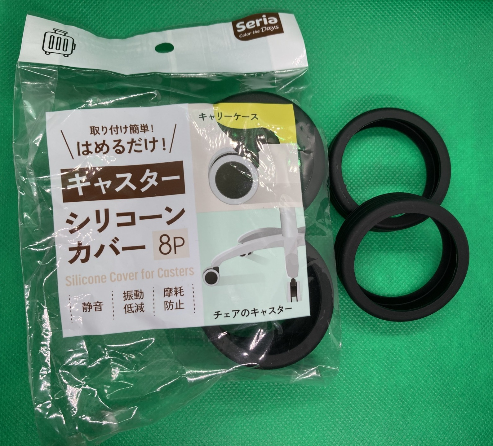
- Caster Protective Silicone Rubber Tires (Seria)

- Bluetooth Remote Control
Elecom VR Remote Controller - Wires, Jumper Cables, Battery (5–9 V)
Hardware Assembly
3D Printing the Chassis and Wheels
Output the design data using a 3D printer to create the wheels and housing. The key point is to secure space on top of the housing to mount the Pi Zero W.
Wiring Motors and Driver Board
Connect VCC/GND of the MX1508 module to the battery supply, and wire IN1/IN2 to the Pi’s GPIOs. Connect the motors to OUT1/OUT2 respectively. Please refer to the official tutorial for the driver board specifications.
Attaching Tires
Attach the 100-yen shop silicone rubber tires to the wheels, place a dummy wheel at the front center, and configure a rear-wheel-drive setup. Rubber tires are effective in preventing slippage.
The Original mBot
Software Setup
Pairing the Bluetooth Gamepad
Scan for the controller using the Raspberry Pi’s bluetoothd, and perform pairing and trust settings.
As there are various challenges regarding Bluetooth connectivity, I plan to post a detailed article at a later date.
Code Explanation
- Input Acquisition (
evdev)- Reads REL_X/REL_Y events from
/dev/input/event2to detect stick tilt and button presses.
- Reads REL_X/REL_Y events from
- PWM Control (
pigpio.hardware_PWM)- Outputs a 50 Hz PWM signal to each GPIO, converting speed commands into duty cycles.
- Differential Drive Calculation
- Calculates left and right motor speeds from throttle and steer values, keeping them within ±100% using clipping.
- Stop & Emergency Stop
- Pressing BTN_LEFT sets a stop flag for all motors to bring them to a prompt halt.
<pre>from evdev import InputDevice, ecodes
from select import select
import time
import pigpio

pi = pigpio.pi()

# PWM 出力用ピンの BCM 番号(横もち)
LEFT_FWD_PIN  = 19  # PWM1_CH1
LEFT_REV_PIN  = 13  # PWM1_CH0
RIGHT_FWD_PIN = 12  # PWM0_CH0
RIGHT_REV_PIN = 18  # PWM0_CH1

# # PWM 出力用ピンの BCM 番号(縦)
# LEFT_FWD_PIN  = 12  # PWM1_CH1
# LEFT_REV_PIN  = 13  # PWM1_CH0
# RIGHT_FWD_PIN = 18  # PWM0_CH0
# RIGHT_REV_PIN = 19  # PWM0_CH1

for pin in (LEFT_FWD_PIN, LEFT_REV_PIN, RIGHT_FWD_PIN, RIGHT_REV_PIN):
    pi.set_mode(pin, pigpio.OUTPUT)  # ハードウェア PWM チャネルを有効

# PWMインスタンス
def set_pwm(pin_fwd:int, pin_rev:int, speed:int):
    """
    pin_fwd: 前進用ピン
    pin_rev: 後退用ピン
    speed: -100~+100 (%)
      +: 前進, -: 後退, 0: 停止
    """
    # PWM 周波数 50Hz とデューティ比(0~1e6)
    FREQ = 50
    if speed >= 0:
        duty = int(speed / 100 * 1000000)
        print('pin: {}, FREQ: {}, speed: {}'.format(pin_fwd, FREQ, duty))
        print('pin: {}, FREQ: {}, speed: {}'.format(pin_rev, FREQ, duty))
        pi.hardware_PWM(pin_fwd,  FREQ, duty)  # 前進デューティを設定
        # pi.hardware_PWM(pin_rev,  FREQ, 0)
        pi.set_mode(pin_rev, pigpio.OUTPUT)
    else:
        duty = int(-speed / 100 * 1000000)
        print('pin: {}, FREQ: {}, speed: {}'.format(pin_rev, FREQ, duty))
        # pi.hardware_PWM(pin_fwd,  FREQ, 0)
        pi.set_mode(pin_fwd, pigpio.OUTPUT)
        pi.hardware_PWM(pin_rev,  FREQ, duty)  # 後退デューティを設定

def set_left_motor(speed:int):
    set_pwm(LEFT_FWD_PIN, LEFT_REV_PIN, speed)

def set_right_motor(speed:int):
    set_pwm(RIGHT_FWD_PIN, RIGHT_REV_PIN, speed)


dev = InputDevice('/dev/input/event2')  # 実際のデバイスに合わせて
dev.grab()  # 排他制御

def read_stick():
    """
    /dev/input/event2 から REL_X/REL_Y のイベントを読み取り、
    SYN_REPORT が来たところで x, y を返す。
    戻り値の x, y は、それぞれ -31 .. +31 の範囲を想定。
    """
    x = 0
    y = 0
    mstop = True

    # デバイスにイベントが来るまでブロック
    r, _, _ = select([dev.fd], [], [])
    if dev.fd in r:
        for event in dev.read():
            # REL_X/REL_Y イベントを足し込む
            if event.type == ecodes.EV_REL:
                mstop = False
                if   event.code == ecodes.REL_X:
                    x += event.value
                elif event.code == ecodes.REL_Y:
                    y += event.value
            elif event.type == ecodes.EV_KEY and event.code == ecodes.BTN_LEFT and event.value == 1:
                # BTN_LEFT が押されたら停止フラグを立てる
                mstop = True
            # SYN_REPORT で一連のイベントが一区切り
            elif event.type == ecodes.SYN_REPORT:
                break

    # 値をクランプ(念のため)
    # x = max(-31, min(31, x))
    # y = max(-31, min(31, y))
    tx = max(-31, min(31, -y))
    ty = max(-31, min(31, x))
    x = tx
    y = ty
    return x, y ,mstop

try:
    while True:
        # 例:スティックの値から -100~+100 の speed を算出
        lx, ly, mstop = read_stick()      # -31~+31 の値を返す想定
        # 前進後退成分
        throttle = int(ly / 31 * 100)
        # 旋回成分
        steer    = int(lx / 31 * 100)

        if(mstop):
            left_speed = 0
            right_speed = 0
        else:
            # 差動走行の左右速度計算
            left_speed  = throttle + steer
            right_speed = throttle - steer

            # クリッピング
            left_speed  = max(-100, min(100, left_speed))
            right_speed = max(-100, min(100, right_speed))

        # モーター出力
        set_left_motor(left_speed)
        set_right_motor(right_speed)

        time.sleep(0.1)

except KeyboardInterrupt:
    # 停止
    set_left_motor(0)
    set_right_motor(0)
    pi.stop()
</pre>
Operation Check and Future Prospects
- Operation Check: Test forward/reverse movement and turns via stick operation on a flat road. Please adjust tire grip and motor response accordingly.
- Improvement Ideas: Speed stabilization via PID control and autonomous navigation for obstacle detection using ultrasonic sensors are conceivable. Web UI control via Wi-Fi and smartphone app integration are also the next steps.
Summary
In this article, we explained everything from the design to the operation of a custom RC car using a Raspberry Pi Zero W, combining low-cost and readily available components. Through creating a housing with a 3D printer and utilizing Python libraries, this content allows you to enjoy robot crafting full of the DIY spirit. Moving forward, let’s aim for further automation by advancing control algorithms and integrating sensors.